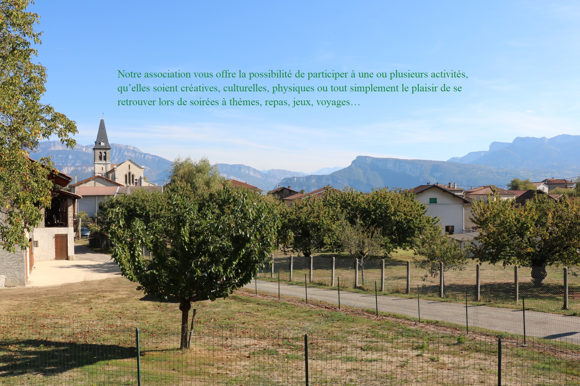
Notre association allie loisirs, détente, culture, découvertes…Par son dynamisme, sa volonté de maintenir une vie associative vivante, conviviale et fraternelle, Charnècles-Loisirs n’a cessé de s’étoffer par son nombre d’adhérents et sa palette d’activités. Nous rejoindre c’est la possibilité de participer à une ou plusieurs d’entre elles ou, tout simplement, le plaisir de se retrouver lors de soirées à thème, repas, jeux, voyages…
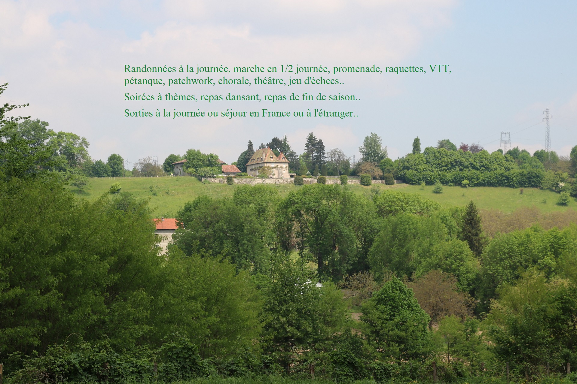
Gilbert PERRAUD en assure la présidence. Chaque section à son propre animateur. Un calendrier, visible sur le site, regroupe les activités proposées chaque jour de la semaine, un autre les événements annuels.